4RUNNER ACCESORY CRADDLE
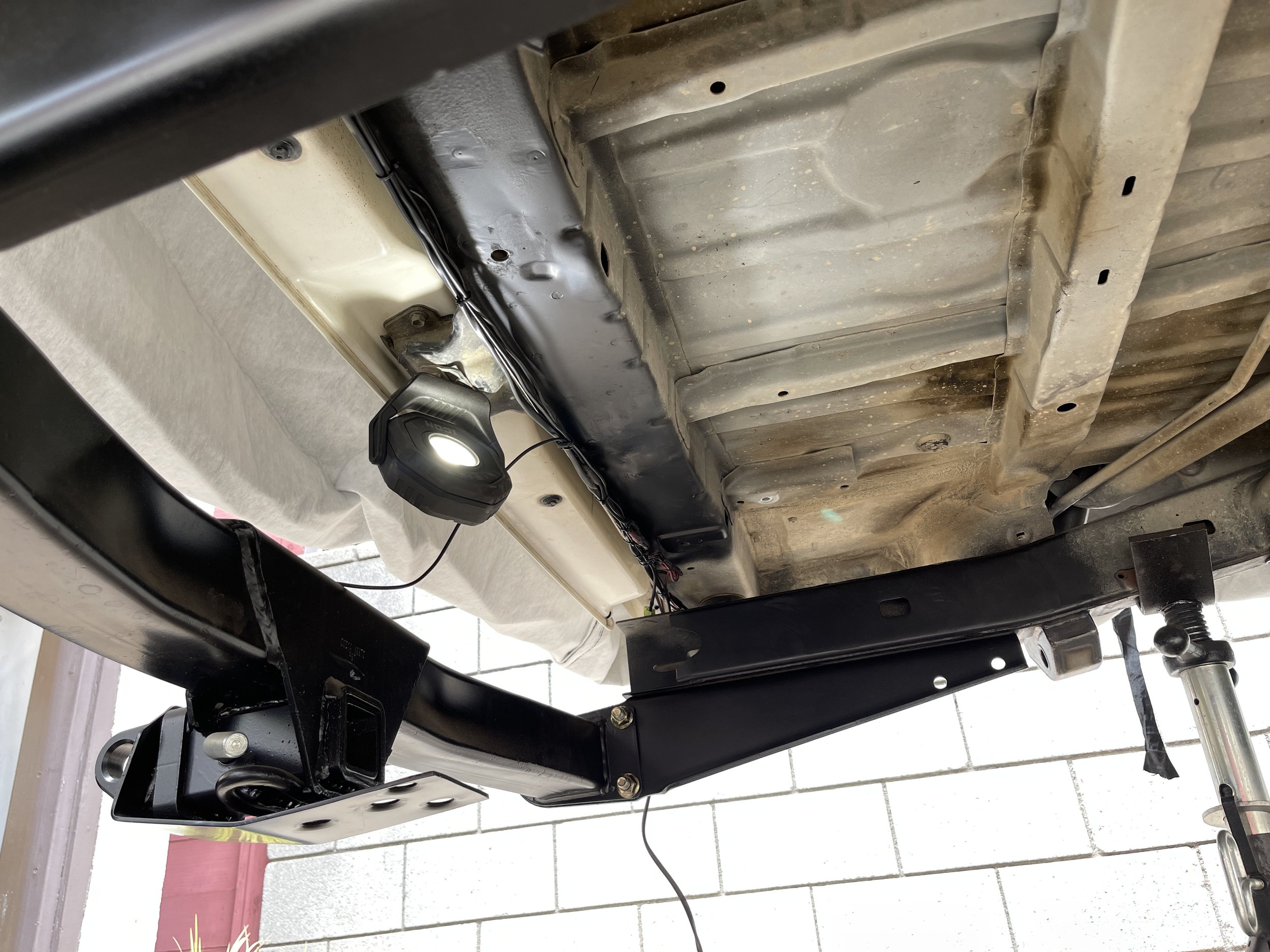
With the 4 Runner project filling out the front and rear fender wells, new work and project is beginning elsewhere within the chassis. Up on the chopping block is the rear undertray and removal of the spare tire. With a blank canvas ahead, I was asked to fit in an air compressor, a large tank, air horns and solenoid, as well as affix the lines for an air-control unit to allow for all 4 corners to fill/deflate as desired.
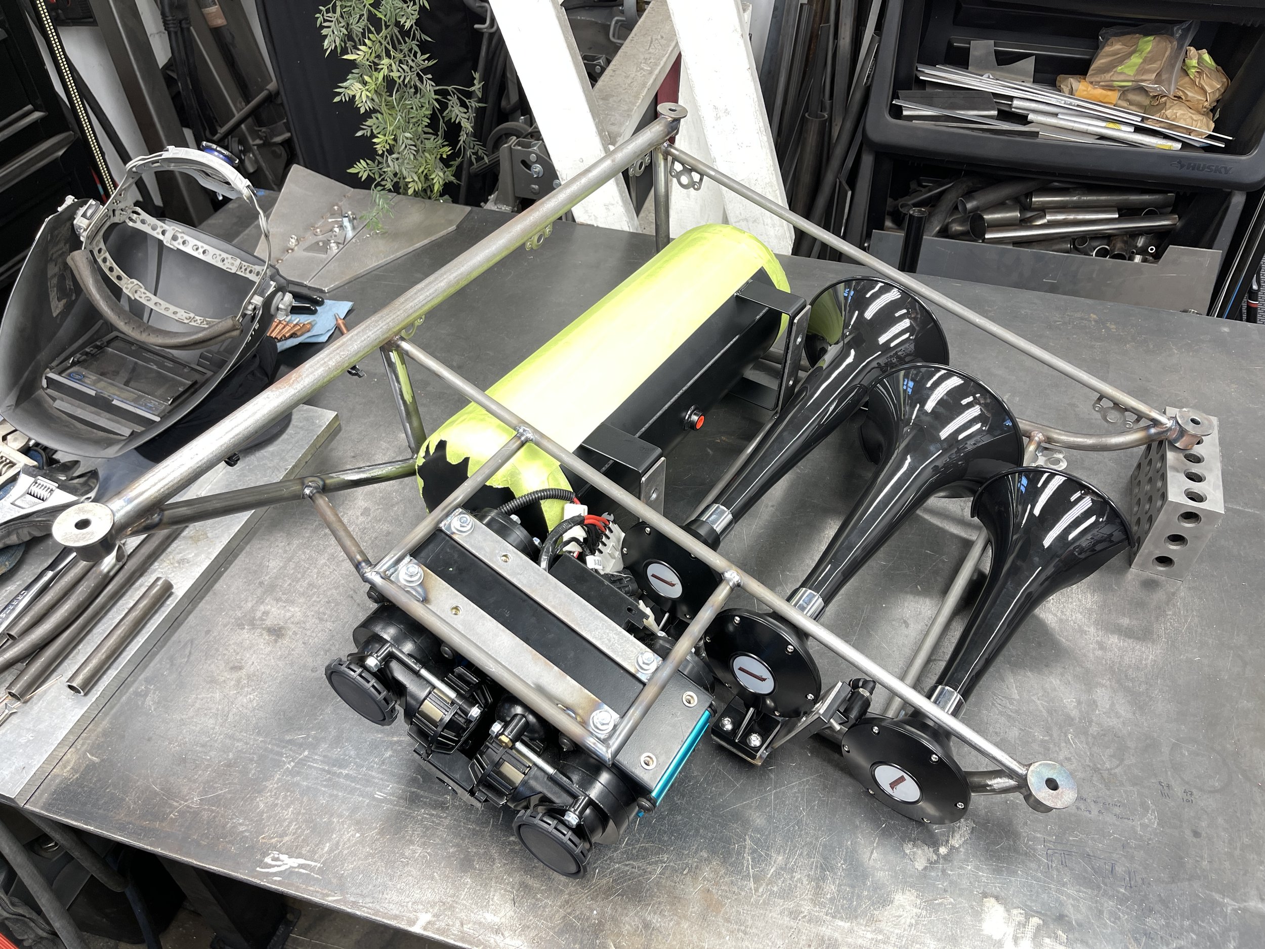
I started with welding up some standoffs that would mount to OEM locations in the rear of the chassis. The accessory tray will mount from these four corners and hang down within the confines of the OEM spare.
The structure features more organic shapes with a long taper from front to back - given that an aftermarket tire swing out bumper will be mounted out back, I wasn’t concerned with a visually impairing departure angle.
With most of the structure tied in together, it was time to start building out the templates to tin out the structure.
Mocked in place and more offset to the driver side, this will help with the weight in the rear as the rear tire swingout will have a 315 tire hanging off the passenger side. This offset also allows to for the last section of the exhaust to route over the pan hard bar brace and lie beside this accessory tray.
This side of the tin work came out great…but would turn out to be trashed as the parts supplied were bigger than anticipated.
The driver side came out great and I was able to add some additional flair with some mesh while allowing for extra air flow as well.
The horns, compressor, and tank…all bigger than expected and in comparison to the parts that were previously used and discussed on a previous build. My process here was to than fit in the tank, move the compressor to the side and brace it, and stagger the horns and notching the trumpets to sit flush amongst each other.
With the structure fully welded out, dzus tabs added and hardware sourced, some steel it paint was sprayed for the perfect looking finish. I had added some more of the mesh in the rear pocket for airflow out of the structure and to visually tie-in both sides together.
All fitted and mounted, the air lines were then ran from the compressor to the tank, each horn was daisy chained together and the wiring was affixed and ready to be ran once mounted in the chassis.
I debated on where to have the air release mounted -underneath and protruding from the bottom seems most fitting but would prove ‘excessive’ to get down there and pull the pin. I opted to have it come out of the side vent for an easier operation whilst still being out of harms way and not visually impairing.
Last up on the build is to re-tin the center section and mount the structure on the chassis.


